
As it should be obvious based on recent posts in this blog, my latest AS3 game prototype thing is a platformer-ish kind of game that uses Nape for physics. I’ve been mentally debating how to approach level design for this game for quite some time.
For a while, I was using the R.U.B.E. Box2D Editor for that. This is an awesome physics/geometry editor that files that are easily converted to Box2D objects, and while I’m not using Box2D, I created a parser function that did the job just fine to run its scenes inside my Adobe AIR-based game.
However, as I started creating the proper levels for my game prototype, it became obvious using R.U.B.E. wasn’t a very fast solution for development. While it is a great editor for physics (and its simulator greatly simplifies the job of testing Box2D scenes), creating the actual geometry, especially curves, is a cumbersome task. This caused me step back and review my level design workflow entirely.
(One of the cool things of building a project on your spare time is being able to throw things away and start it from scratch.)
To me, the best way to edit simple geometry based on lines or curves would be to use a vector editor like Adobe Illustrator. This is a program I have been using for a very long time, and that I frankly enjoy. Its polygon editing tools are top notch, its keyboard shortcuts are deeply burned into my brain, and certain features such as boolean editing would be extremely convenient for the kind of level design I had in mind.
I toyed with the idea of editing basic geometry inside Illustrator and exporting the vertex data via scripts. This is quite possible, but also cumbersome. Instead, the solution I found was obvious in hindsight: editing a SVG file with Illustrator, and then using this file directly to define my level geometry.
Level editing in illustrator
This solution has one disadvantage: the inability to easily add any kind of metadata – such as surface material and other physics properties – to shapes I create inside the editor (the SVG format would certainly allow that, but there’s just no easy way for me to edit that from Illustrator). My certifiably ghetto solution was encoding certain properties in the object’s id (its “layer name”), since this id is also saved in the SVG file.
I have spent a few days building and toying around this solution and it seems to be a very powerful way of doing level editing. The workflow goes like this:
- Edit a document in Illustrator, creating any shapes desired. The shape properties – such as fill color, or stroke properties – do not matter. Some items are used as especial entities (rather than geometry), and lines are used for joints.
- Save it as an SVG.
- The game loads the SVG (as a XML) and parses all polygons found, as well as its metadata (from each object’s id). This is not done using a SVG library, but rather parsing the actual raw path data for each shape type.
- The game engine reads the level geometry data and creates both the physics geometry necessary (using Nape) and the actual level rendering (which is largely generative). Some metadata (such as level start and level end entities) come from shapes identified as such, and joints are automagically created from lines depending on how they’re used and number of points in them.
This workflow requires very few steps for level editing iteration. I can just edit something in Illustrator, save the file, switch back to my development IDE, run my prototype, and the level is loaded with no pre-processing or exporting necessary.

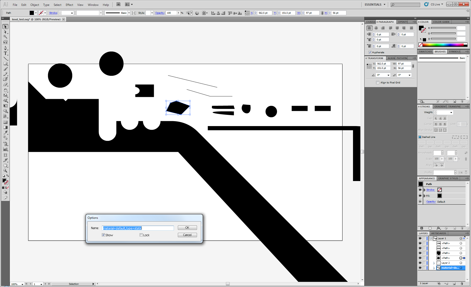
Running level inside the game
The above screenshot shows my current test level, as-is, running inside the game. It looks somewhat strange because it’s drawing the raw level geometry using Nape’s debug render. The polygons had to be subdivided, to avoid concave polygons; of course, this will change once the actual level renderer is in place.
And here’s a video showing the level being played, using the first implementation of the level renderer:
One great feature of this workflow is that since curves are represented as curves inside my level file, it’s up to the game code to decompose this curve into line segments (Nape, as most physics engines, do not support curved geometry). And by “great feature” I mean that I can control how precise the curves are, that is, how many lines are created from each curve (and as it turns out, this is one of the pieces of code in this game I’m most proud about).
Decomposing a curve into several line segments is not really a mystery Рthe equation for doing so based on the cubic b̩ziers used by the SVG format can be found on Wikipedia, and indeed, I already had a function that allowed me to do so.
The crux of the problem is finding the right amount of precision. It’s easy to control the precision of a curve decomposition by simply varying the number of segments you’ll be using when recreating it with lines. However, if you use a fixed number of segments per curve, it means that both very tight curves and gentle slopes will have the same number of segments, as well as not taking the curve’s scale into account. I needed to strike a balance good performance (fewer segments per curve means an easier job for the physics engine) as well as still looking good if the player was moving around a curve (no discernible corners). This would mean treating different curves in different ways. This prototype is supposed to run on low-end, mobile platforms (such as Android and OUYA), after all; the performance budget is not very large.
The solution I got to (after 2 fun-but-not-so-efficient attempts) is a function that decomposes cubic béziers into line segments based on a maximum error parameter. What it does is keep creating segments in a curve until no point in the created segments drifts too far from where they would originally be at, were they still present in the original curve.
(I like to think of this solution as my own Quake 3 curved surface breakthrough.)
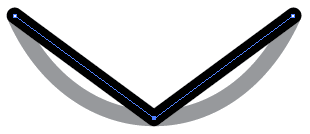
For example, consider this curve represented as a standard cubic bézier:

The first thing the algorithm does is try to use a single segment for it. In this case, it just uses a line going from the curve start to its end.

After doing so, it measures the distance from the middle of the new segment, to the middle of the curve.

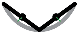
If this distance is higher than the maximum error allowed – which is determined in pixels, or whatever units the curve coordinates use – the algorithm decides using only one segment, after all, isn’t good enough. So it starts again, this times using two segments. The vertices of the segments are uniformly distributed over the curve. In this case, it would look like this.
After doing so, the algorithm tests the segments again. Now, there is more than one segment to test, so the algorithm measures the distance of the mid-point of all segments.
If the distance is still more than the desired distance, it then creates even more segments. It doesn’t simply create new points in the middle of the previous segments, though. Doing so would produce a pretty accurate group of segments, no doubt, but those would frequently be more than the number of vertices needed. That’s because the number of segments tested would increase exponentially, rather than linearly. Instead, the algorithm discards all existing points and tries it again with one segment more than before. This means it tries using 3 segments next.
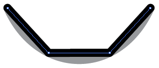
It continues doing so, checking the distance of the middle points, until it thinks the resulting group of segments is close enough to the original curve. For example, the result with 8 segments could look like something like this, depending on the maximum error distance allowed:
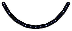
Which may not look close enough at this zoom level, but is certainly passable if this curve is, say, 50 pixels wide. Again, the important point here is being precise enough for its intended size, and no more than that. Having a “maximum error distance” based in pixels is the right way to do it.
The code for this function looks like this:
private function createVerticesForCubicBezierMiddle(__start:Point, __control1:Point, __control2:Point, __end:Point):Vector.<Point> {
	// Based on control points and target points, create lines to decompose
	// a single cubic bezier with fixed precision; returns the vertices of those lines

	// How far any point in the news segments can be from the curve, using the curve units (i.e. pixels)
	const MAX_CURVE_DECOMPOSITION_ERROR:Number = 0.2;

	// Create a cubic bézier to make things easier
	// Uses http://github.com/zeh/as3/blob/master/com/zehfernando/geom/CubicBezierCurve.as
	var curve:CubicBezierCurve = new CubicBezierCurve(__start, __control1, __control2, __end);

	var vertices:Vector.<Point> = new Vector.<Point>();

	// Create items until the error distance for all segments is smaller than the maximum allowed
	var i:int;
	var segments:int = 1; // Start with 1, which is a possible solution if the curve is very straight
	var maxError:Number = NaN; // Maximum distance found
	var currentError:Number; // Distance between test points
	var pCurve:Point; // Test point in the curve
	var pSegment:Point; // Test point in the segment
	var maximumSegmentsAllowed:int = 100; // Last resort (shouldn't be necessary save for humongous curves)
	while ((isNaN(maxError) || maxError > MAX_CURVE_DECOMPOSITION_ERROR) && segments < maximumSegmentsAllowed) {
		vertices.length = 0;
		maxError = 0;

		// Create line
		vertices.push(__start);
		for (i = 1; i < segments; i++) {
			vertices.push(curve.getPointOnCurve(i/segments));
		}
		vertices.push(__end);

		// Verify error distance by checking the middle of every segment
		for (i = 0; i < vertices.length-1; i++) {
 			pSegment = Point.interpolate(vertices[i], vertices[i+1], 0.5);
 			pCurve = curve.getPointOnCurve((i+0.5)/segments);
 			currentError = Point.distance(pSegment, pCurve);
 			if (currentError > maxError) {
				maxError = currentError;
			}
		}

		segments++;
	}

	// Additional check to see if any of the existing vertices is removable
	// This is not strictly necessary but can happen for some curves
	for (i = 0; i < vertices.length-2; i++) {
		pSegment = Point.interpolate(vertices[i], vertices[i+2], 0.5);
		pCurve = curve.getPointOnCurve((i+1)/segments);
		currentError = Point.distance(pSegment, pCurve);
		if (currentError < MAX_CURVE_DECOMPOSITION_ERROR) {
			// Can remove this item
			vertices.splice(i+1, 1);
			i--;
		}
	}

	return vertices;
}
This is a first pass at the problem and the code can probably be optimized. However, this is only called once – when parsing the level data – and it’s unlikely to be a performance hog until the level reach a much higher level of complexity. I’ll eventually roll this function into the CubicBezierCurve class, though, so I’ll probably do some performance enhancements then.
Once decomposed into a list of points (a polygon), this data can be used to create shapes in Nape. This is accomplished by using Nape’s own GeomPoly class, since it implements a decomposition function to avoid convex polygons.
// "vertices" contain the list of points, converted to a Vector of Vec2
var geom:GeomPoly = GeomPoly.get(vertices);
var gpl:GeomPolyList = geom.convexDecomposition(true);
gpl.foreach(function(poly:GeomPoly):void {
	shapes.push(new Polygon(poly));
});
All shapes are then added to a Body that is then added to a Nape Space instance and the simulation can begin. A slightly different version of this data is also fed into the level renderer, but this is material for another topic (and I haven’t finished the renderer yet).
While I’m sure that many more scholarly solutions exist to solve the curve decomposition problem, getting to the solution that best fit my needs (and the fun involved with finding it) is half the reason why I’m developing this prototype. I’ll write more about that in the future; for now, I’m surprised at how pleasant and fast editing an SVG can be for basic level design, and something I would recommend more people exploring depending on their needs.
Hey Fernando, thank you for sharing this. Very interesting approach!
Hi Fernando, thanks for sharing – it made my day happy as I’m trying to implement your approach for flash pro. THX! 🙂